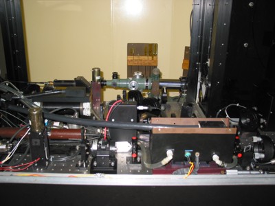
Laser main table.
The laser subsystem uses a Q-switched laser transmitter to produce laser pulses with a 532 nanometer wavelength at a 1-, 2-, 4-, and 5-pps rate with a pulse width of 200 picoseconds. Output beam divergence from the amplifier in the laser transmitter is less than 5 milliradians. Laser beam expanders are used to reduce beam divergence to 0.2 milliradians.
Laser
main table.
The power supplies produce and distribute both AC and DC power, plus charging currents, to pulse forming circuits that activate the laser head flash lamps. Local control of the lasing operation is provided at the control unit. External control lines connect the laser external on/off interlock and firing rate selector to the LRC chassis in the DMS subsystem. Laser fire rate, and emergency stop are controlled from the DMS console. Emergency stop can also be controlled from the optical mount, the optical platform, and the laser clean room. Laser cooling is provided by an external closed cycle cooler, which pumps coolant through the laser head. (See Figure 1-1.)
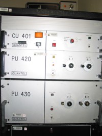
View
of laser rack.
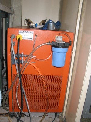
Laser
cooler.
Pulse Forming. After the oscillator (6) fires, the light pulse reflects back and forth between the etalon (8) and the dye cell (3) until the dye cell bleaches. At that time, the light reflects off the mirror at the back of the dye cell and passes through the etalon. The pulse then reflects off two mirrors and passes through a beam expander enroute to the pulse slicer (11). From the pulse slicer, the light pulse reflects off specialized mirrors before passing through the dielectric polarizer (15). The light then enters the double-pass amplifier (17), where it reflects off a mirror (18) and passes back through the amplifier to the dielectric polarizer. Now amplified and polarized, the pulse reflects off the polarizer. It then passes through the frequency doubler (20), where the light becomes visible. After being reflected to change its routing, the beam enters the final beam expander on the laser table, and it leaves the clean room. From there it is routed to the transmit optics by the coude mirror train.
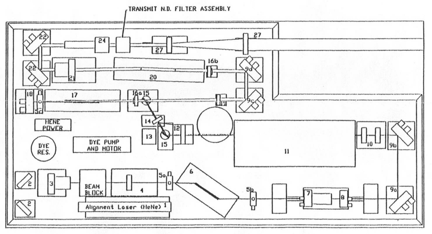
Figure
1-1: Laser pulse forming schematic diagram.
Range Timing. When the photodiode detects the laser output pulse as described above, it outputs a pulse to the transmit side of the DMS subsystem delay box circuit for input to the REM. The laser output pulse starts range TIC in the DMS.
Upon generation, the MOBLAS 6 laser beams have a wavelength of 1064 nanometers. This places them in the infrared spectrum. The human eye is insensitive to infrared wavelengths; they cannot be seen. However, at the energy levels present in the beam, the beams can - and will - do severe damage to the eye. They can literally cook the retina - irreversibly. It is not until the laser beam passes through the frequency doubler that it becomes visible to the eye. Even then it carries extremely dangerous power levels, and can put blind spots in a person's eye at ranges beyond 35 kilometers.
Optical Attenuation Mechanism (OAM). The OAM works in both the transmit and receive paths to provide both manual and automatic attenuation of laser pulse brightness. Transmit attenuation is set once, usually during system installation, and is used to ensure personnel safety whenever transmitting at angles below 20° above the horizon. Transmit attenuation is used mostly when performing system calibrations on known targets. It is not used when ranging on satellites. Receive attenuation varies under operator control, and is constantly variable, and is used when ranging to satellites.
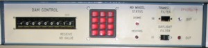
OAM
control subsystem.